Email id : info@duexin.in


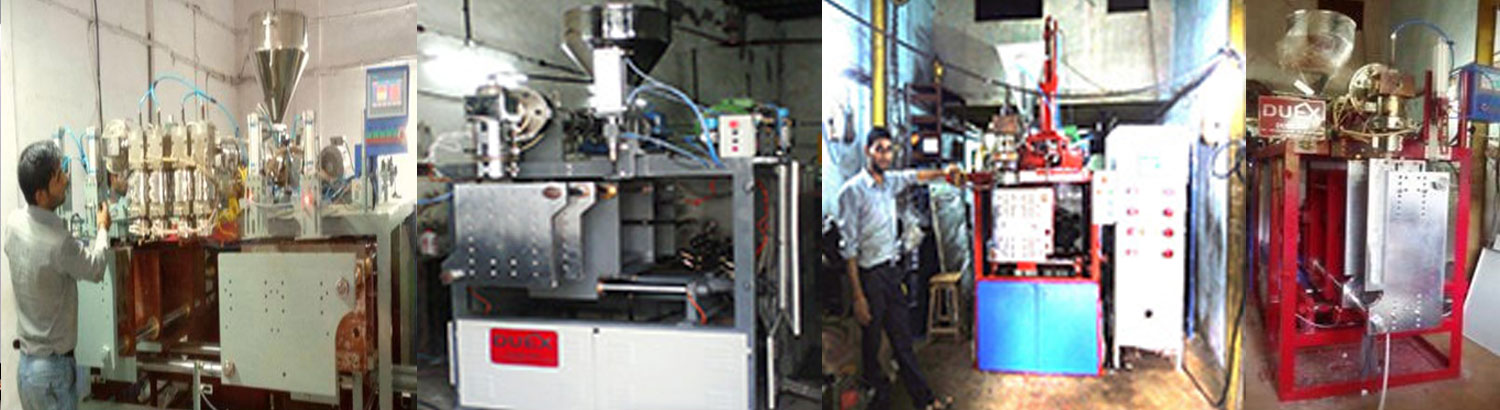
In Extrusion blow moulding (EBM), plastic is melted and extruded into a hollow tube (a parison). This parison is then captured by closing it into a cooled metal mould. Air is then blown into the parison, inflating it into the shape of the hollow bottle, container, or part. After the plastic has cooled sufficiently, the mould is opened and the part is ejected.
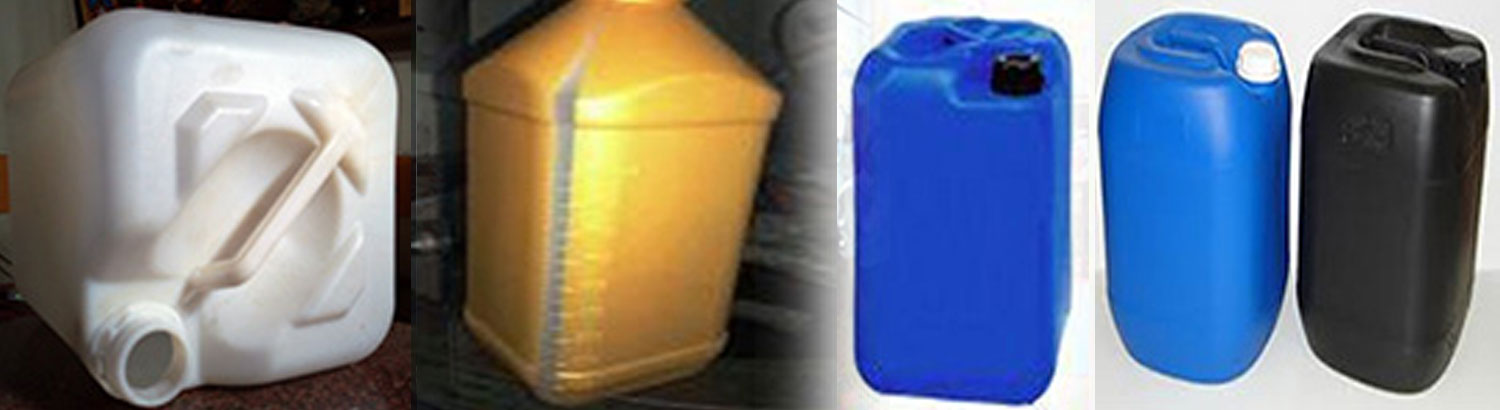
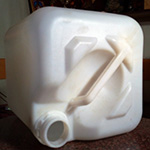
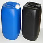
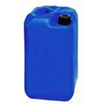
EBM processes may be either continuous (constant extrusion of the parison) or intermittent. Examples of parts made by the EBM process include most polyethylene hollow products, Milk bottles, shampoo bottles, Automotive ducting, watering cans and hollow industrial parts such as drums.
Advantages of blow moulding include: low tool and die cost; fast production rates; ability to mould complex part; Handles can be incorporated in the design.
Disadvantages of blow moulding include: limited to hollow parts, low strength, to increase barrier properties multilayer parisons of different materials are used thus not recyclable. To make wide neck jars spin trimming is necessary.
The process of injection blow Moulding (IBM) is used for the production of hollow glass and plastic objects in large quantities. In the IBM process, the polymer is injection Moulded onto a core pin; then the core pin is rotated to a blow Moulding station to be inflated and cooled. This is the least-used of the three blow Moulding processes, and is typically used to make small medical and single serve bottles. The process is divided into three steps: injection, blowing and ejection.
Advantages: It produces an injection Moulded neck for accuracy.
Disadvantages: only suits small capacity bottles as it is difficult to control the base centre during blowing. No increase in barrier strength as the material is not biaxially stretched. Handles can't be incorporated.
This has two main different methods, namely Single-stage and two-stage process. Single-stage process is again broken down into 3-station and 4-station machines In the two-stage injection stretch blow Moulding (ISB) process; the plastic is first Moulded into a "preform" using the injection Moulding process. These preforms are produced with the necks of the bottles, including threads (the "finish") on one end. These preforms are packaged, and fed later (after cooling) into a reheat stretch blow Moulding machine. In the ISB process, the preforms are heated (typically using infrared heaters) above their glass transition temperature, then blown using high-pressure air into bottles using metal blow Moulds. The preform is always stretched with a core rod as part of the process.
Advantages: Very high volumes are produced. Little restriction on bottle design. Preforms can be sold as a completed item for a third party to blow.
Disadvantages: High capital cost. Floor space required is high. Only suits round bottles
Injection Moulding machines can fasten the Moulds in either a horizontal or vertical position. The majority of machines are horizontally oriented, but vertical machines are used in some niche applications such as insert Moulding, allowing the machine to take advantage of gravity. Machines are classified primarily by the type of driving systems they use: hydraulic, mechanical, electric, or hybrid.
Hydraulic presses have historically been the only option available to Moulders until Nissei Plastic Industrial Co., LTD introduced the first all-electric injection Moulding machine in 1983. Hydraulic machines, although not nearly as precise, are the predominant type in most of the world, with the exception of Japan.
Mechanical type machines use the toggle system for building up tonnage on the clamp side of the machine. Tonnage is required on all machines so that the clamp side of the machine does not open (i.e. tool half mounted on the platen) due to the injection pressure. If the tool half opens up it will create flash in the plastic product. Reliability of mechanical type of machines is more as tonnage built.
The electric press, also known as Electric Machine Technology (EMT), reduces operation costs by cutting energy consumption and also addresses some of the environmental concerns surrounding the hydraulic press. Electric presses have been shown to be quieter, faster, and have a higher accuracy; however the machines are more expensive.
Hybrid injection (sometimes referred to as "Servo-Hydraulic") Moulding machines claim to take advantage of the best features of both hydraulic and electric systems, but in actuality use almost the same amount of electricity to operate as a standard hydraulic, A robotic arm is often used to remove the Moulded components; either by side or top entry, but it is more common for parts to drop out of the Mould, through a chute and into a container.
The custom-pak blow Moulding design guide provides you with basic design tools for making engineered blow Moulded parts. This guide focuses on the extrusion blow Moulding process. No two designs are alike, so the Mould and process must be adjusted to optimize each design. Software products can help predict Moulding characteristics and our engineers are here to help make your product great. Our design assistance is confidential and free.
Blow Moulding is a simple five-step sequence.
The first step involves mixing, melting and pushing plastic (extrusion) to form it into a tube called a parison that will be used to make the part.
Material selection is a critical aspect of design and should involve serious study of:
In order to design a blow-Moulded product, you must understand the interaction between the molten plastic parison and the Mould. If you’ve blown a bubble from bubble gum you can understand blow Moulding. The plastic material stretches like the gum and if it gets too thin it ruptures. Since the parison is extruded as a tube, it is easy to make a tube or bottle shaped part, not much stretching occurs. The two Mould halves open, the parison is inserted, the Mould halves close and the part is blown. The split between Mould halves is known as the parting line. There is often a knife like edge on the parting line around the part shape known as pinch-off.
If the part shape to be Moulded is changed from a tube into a flat panel type part, the parison tube must be flattened to make the panel. When this happens the circumference of the parison becomes the surface that needs to cover the width of the panel. So we try to have a large enough parison diameter that as it flattens, it can be captured by the entire perimeter of the panel at the pinch-off. If the parison does not extend to all areas of the pinch-off, it must stretch the rest of the way.
The soft plastic can stretch only a short distance before it begins thinning. Like the bubble gum, the first thin spot is weakest and it gets thinner fastest until it pops. If the plastic parison pops it is called a “blow-out” and results in no part formation at all.
As the complexity of the part progresses to double-wall shapes with side walls and inner contours, the parison must not only be captured at all points along the parting line, but it must also meet the material thickness needs for the variety of Moulding conditions specific to each area of the part. Many of the design criteria used to make a tray with Moulded inner shapes will be the same for designing a complex industrial part.
The inner and outer walls of the part are formed simultaneously and integrally, but interior and exterior designs are essentially independent so we review them separately. As the design develops, the designer should begin thinking about the interaction of the plastic and the Mould that will produce the part. The visual exterior of many products is formed in one half of the Mould called a cavity.
The interior surface of double-wall blow Moulded parts is normally formed by a Mould core. Since the Mould core must fit inside the cavity, there should be no question it meets the same W>2D overall size requirement as the cavity.
The half of the parison that is draping over the Mould core is already beginning to set as the air is injected into the parison. As in the cavity, the plastic begins to stretch to fit the Mould contour. Almost no flow occurs. Unlike the cavity, some different rules apply.
It is the combination of closing the Mould on the parison and the expansion of air inside the parison that forms the part. The designer must leave sufficient space between the inner and outer part surfaces to permit adequate blowing of air into every square inch of the part. If the air passage inside the part is reduced or obstructed, the part will not form.
The double walls in blow Moulded parts provide engineers with a tremendous opportunity to create structure within the plastic part. A properly designed double-wall part will be substantially stronger than a ribbed single-wall part of equal weight and can easily outperform metals in many applications. There are several ways to add strength to blow Moulded part designs.
There are a limitless number of secondary operations that can be performed on a blow-Moulded part to meet the needs of the finished product. Drilling, sawing, milling, cnc routing, die cutting, punching, riveting, screwing, sonic, spin or heat welding, and surface treating are common operations. Nearly any secondary step can be performed economically if the right equipment is available. A surprising number of operations can be done in-Mould. Custom-Pak provides a huge variety of secondary operations equipment at no charge. There are many ways to get the appearance that you want in your blow Moulded parts. We can help you make sure your design will look great long after the consumer has made their purchase.
| Machine | Unit | BMM 200 |
BMM 500 |
BMM 1000 |
BMM 3000 |
BMM 5000 |
BMM 10000 |
| Rating | M1 | 200 | 500 | 1000 | 3000 | 5000 | 10000 |
| Screw Diameter | MM | 35 | 40 | 45 | 50 | 65 | 75 |
| Length Diameter Ratio | L/D | 22 | 22 | 22 | 22 | 22/24 | 22/24 |
| Maximum plasticizing capacity | KG/HR | 8-10 | 12-15 | 16-20 | 25-28 | 45-50 | 60-80 |
| Extruder Motor (Variable) | HP/KW | 3/2.2 | 5/3.7 | 7.5/5.5 | 10/7.5 | 15/11 | 25/18.5 |
| Heating Load | KW | 3.0 | 4.2 | 5.6 | 8 | 10.5 | 15 |
| Maximum Screw Speed | RPM | 50 | 50 | 50 | 50 | 50 | 50 |
| Heating Load | KW | 2.0 | 2.0 | 4.5 | 5.8 | 8.4 | 12 |
| Parison control cylinder | DIA | -- | -- | -- | 3 | 5 | 8 |
| Die core size (min/max) | MM | 5/30 | 5/40 | 20/80 | 20/110 | 60/160 | 100/200 |
| Maximum opening | MM | 250 | 300 | 355 | 465 | 510 | 800 |
| Minimum | MM | 150 | 150 | 150 | 155 | 155 | 200 |
| Mixmum mold size - MM | W x H | 125 x 175 | 150 x 250 | 220 x 320 | 300 x 350 | 350 x 450 | 500 x 700 |
| Mould Clamping Unit | TON | 1 | 1 | 2 | 5 | 8 | 10 |
| Hydraulic Drive Motor | HP/KW | 3/2.2 | 5/3.7 | 5/3.7 | 7.5/5.5 | 10/5.5 | 15/11 |
| Oil Tank Capacity | LTR | 90 | 150 | 150 | 190 | 240 | 350 |
| Mixmum mold size - MM | W x H | 125 x 175 | 150 x 250 | 220 x 320 | 300 x 350 | 350 x 450 | 500 x 700 |
| Mould Clamping Unit | TON | 1 | 1 | 2 | 5 | 8 | 10 |
| PRODUCTION | PCS/HR | 330 - 360 of 15 gm |
250 - 300 of 30 gm |
220 - 240 of 60 gm |
160 - 180 of 120 gm |
130 - 135 of 220 gm |
200 - 300 of 300 gm |
| DELIVERY | WEEKS | 5 | 5 | 5 | 5 | 6 | 8 |
| POWER | HP/KW | 13/10 | 18/10 | 29/22 | 36/27 | 51/38 | 75/55 |
| BMM Dimn (L x H x W) | Feet | 6 x 5 x 6 | 7 x 4.5 x 6.5 | 7 x 4.5 x 7.5 | 9 x 4.5 x 8.5 | 10.5 x 5 x 5.5 | 15 x 7 x 10 |
| Electrical Panel Dimn L x H x W) |
INCH | 16 x 36 x 51 | 16 x 36 x 51 | 17 x 44 x 63 | 16 x 36 x 51 | 16 x 36 x 51 | 20 x 50 x 80 |
| Machine Weight (Approx) |
TONS | 0.8 | 1.6 | 2.1 | 3.20 | 4 | 6 |
| Digital Display | Std | Std | Std | Std | Std | Std |
| Cutting System | Std | Std | Std | Std | Std | Std |
| VFD (Extruder) | Std | Std | Std | Std | Std | Std |
| Filter, Regulator & Lubrication for pneumatic | Std | Std | Std | Std | Std | Std |
| Helical Gear Box | Std | Std | Std | Std | Std | Std |
| Artical Collecting Tray | Std | Std | Std | Std | Std | Std |
| Safety Guard | Std | Std | Std | Std | Std | Std |
| Yuken Hydraulics | Std | Std | Std | Std | Std | Std |
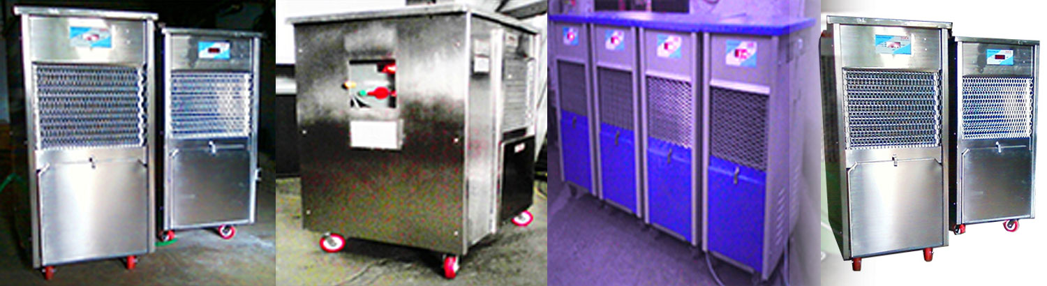
| Water Chiller | Opt | Opt | Opt | Opt | Opt | Opt |
| Air Dryer | Opt | Opt | Opt | Opt | Opt | Opt |
| Electrical Pistons | Opt | Opt | Opt | Opt | Opt | Opt |
| Hot Wire Cutting | Opt | Opt | Opt | Opt | Opt | Opt |
| Three Stage Parison Progrom | Opt | Opt | Opt | Std | Std | Std |
| Multipoint Parison Progrom | Opt | Opt | Opt | Opt | Opt | Opt |
| View Strip Attachment | Opt | Opt | Opt | Opt | Opt | Opt |
| Energy Meter | Opt | Opt | Opt | Opt | Opt | Opt |
| Hopper Loader | Opt | Opt | Opt | Opt | Opt | Opt |
| Leak Testing Arrangement | Opt | Opt | Opt | Opt | Opt | Opt |
| Auto Lubrication | Opt | Opt | Opt | Opt | Opt | Opt |
| Hydraulic Blowpin | Opt | Opt | Opt | Std | Std | Std |
| Double Head Attachment | Opt | Opt | Opt | Std | Std | Std |